Everything you need to know about 3D reconstruction techniques
Summary – TLDR
- 3D reconstruction techniques are emerging as powerful tools for industrial inspection.
- These techniques create detailed digital replicas of objects, allowing examination from every angle.
- The benefits include high-resolution models that catch defects early, automated inspections, remote examination and lower costs. They provide permanent records, enable advanced AI analysis and improve quality assurance across a range of industries.
- These technologies come with a lot of technical terms that can get hard to follow. This article aims to clarify the most common ones.
Inputs for 3D reconstruction:
- Images: photographs taken from various viewpoints.
- Videos: video frames used as images, though of lower quality.
- Point clouds: collections of 3D points from LiDAR or structured-light scanners.
- Depth data: information on the distance between the sensor and the object’s surface.
Outputs of 3D reconstruction:
- Sparse point cloud: an initial capture of the essential structure.
- Dense point cloud: a detailed representation with a high density of points.
- Mesh: a web-like structure for efficient storage and rendering.
- Neural rendering: high-quality images and video from any angle, via neural networks.
3D reconstruction processes:
- Active sensing techniques:
— Structured light scanning: projects light patterns and analyses the distortions. — Time-of-Flight (ToF) cameras: use pulsed light to measure depth. — LiDAR scanning: uses lasers to measure distances and generate point clouds.
- Image-based 3D reconstruction:
— Photogrammetry: extracts 3D information from 2D images. — Structure from Motion (SfM): analyses image features to derive 3D structure. — Multi-view Stereo (MVS): generates dense point clouds from image sets.
- Image-based rendering:
— Neural Radiance Fields (NeRFs): use deep learning for photorealistic renders. — Gaussian Splatting: renders 3D point cloud data smoothly.
Combining techniques:
- Often, the best result comes from combining different techniques to get the most out of each.
For those with time to read, here it is.
Traditional industrial inspection rests on human expertise and specialized tools. But 3D reconstruction techniques are emerging as powerful tools for inspectors. These techniques create detailed digital replicas of objects, allowing close examination from any angle.
These technologies bring many advantages, including high-resolution models that capture fine detail, ensuring defects are caught early. Automated inspections save time and labour, allowing more frequent monitoring. Inspectors can examine the models remotely, improving safety and making it easier to involve experts from anywhere in the world. That reduces labour costs and prevents expensive repairs.
What’s more, 3D models provide permanent records for tracking changes, planning maintenance and complying with regulations. They also enable advanced analysis with AI, giving deep insight into potential problems. From manufacturing to construction to the energy sector, 3D reconstruction improves quality assurance and structural monitoring, making inspections more accurate, more efficient and more cost-effective.
But in a landscape of emerging technologies, AI and technical terms, it can be hard to understand what’s what. This article aims to clarify the common terms in 3D reconstruction and give a general sense of what they’re used for.
1. The inputs
The first thing to consider in 3D reconstruction is the inputs. These can be:
- Images: photographs taken from various viewpoints around the object of interest. Photogrammetry, a widely used technique, relies on overlapping images to reconstruct 3D structure.
- Videos: a video moving through different viewpoints of the object of interest. This can then be split into individual frames and treated as images. It has the advantage of being faster to capture in the field, but video frames are generally lower quality than photos taken by hand.
- Point clouds: collections of 3D points representing an object’s surface. These can come from LiDAR scanners, which use lasers to measure distance, or from structured-light scanners that project patterns onto the object.
- Depth data: information on the distance between the sensor and each point on the object’s surface. This data can be captured by specialized cameras or combined with image information.
The choice of input data depends on the specific application and the level of detail wanted. For example, inspecting a simple object might use images from several angles, while very complex components may need the precision of LiDAR scans.
The 3D reconstruction process then takes those inputs and turns them into a digital representation of the object. That can be:
- Sparse point cloud: in some workflows, the reconstruction process may initially generate a sparse point cloud to capture the essential 3D structure. That can be a valuable intermediate step for tasks such as camera calibration or rough dimension estimation, before moving to a denser point cloud for detailed analysis.
- Dense point cloud: a large number of densely grouped points, creating a more detailed and accurate representation of the object’s surface.
- Mesh: a collection of vertices (points) connected by edges and faces to form a surface. Picture a web-like structure defining the object’s overall shape. Meshes are efficient for storage and rendering, which makes them well suited to visualization and analysis, but they are lower quality than dense point clouds.
- New video and images via a neural network: while they don’t create a traditional 3D model, some techniques can produce high-quality photo and video renders of an object from any angle. This is generally achieved through neural rendering techniques, explained below.
The different processes for carrying out 3D reconstruction
With inputs and outputs out of the way, we need to talk about the different processes that can carry out 3D reconstruction.
- Active sensing techniques: techniques that actively project light or other signals onto the scene and analyse the response to reconstruct 3D structure. The most common technologies in this category are:
— Structured light scanning: — This technique projects a known light pattern (often stripes or grids) onto the object’s surface. Specialized cameras capture the deformed pattern, and software analyses the distortions to compute the 3D structure. Structured light scanning offers high precision and detail for capturing complex shapes, making it particularly suited to intricate industrial components. — Common applications: electronics manufacturing, automotive manufacturing, medical applications, and so on. — Common libraries/software/tools: Artec Studio, GOM Inspect, Radiant Studio, and others. — Time-of-Flight (ToF) cameras/sensors: — ToF cameras use a pulsed light source, generally infrared, to measure the time light takes to reach an object and come back. By analysing that time-of-flight data for each pixel on the sensor, a depth map of the scene is generated. ToF cameras offer real-time depth sensing, making them suited to applications such as gesture recognition and robotics. — Common applications: gesture recognition, robotics, 3D scanning and mapping, security and surveillance, virtual and augmented reality, autonomous vehicles, and so on. — Common libraries/software/tools: OpenCV, Open3D, PCL, RealSense, and others. — LiDAR scanning — LiDAR (Light Detection and Ranging) is the most common example of ToF sensors. It uses pulsed lasers to measure the distance to an object’s surface from a fixed location. By rotating the scanner or moving it around the object, an extremely precise and detailed point cloud is generated. LiDAR excels at capturing complex geometry and works well even in low light, making it a powerful tool for industrial inspection work. — Common applications: industrial inspection, autonomous vehicles, infrastructure management, topography and surveying, and so on. — Common libraries/software/tools: CloudCompare, MeshLab, Geomagic Control X, PolyWorks, and others. — Other technologies include digital fringe projection (DFP), radar and more.
- Image-based 3D reconstruction: techniques in this category rely solely on analysing the information captured in the images themselves, such as identifying matching features or estimating camera positions.
— Photogrammetry — Photogrammetry is a family of techniques used to extract geometric information from 2D images or photographs. By analysing features and matching corresponding points across multiple images, photogrammetry reconstructs the scene’s 3D structure and surface geometry. — Common applications: architectural modelling, cultural heritage preservation, video games, film visual effects, drone mapping and surveying, product design and manufacturing. — Common libraries/software/tools: Meshroom, Autodesk ReCap, Bentley ContextCapture, Metashape, and others. — Structure from Motion (SfM) — SfM is a foundational element of photogrammetry. This step analyses matching features across multiple images to determine camera positions and the locations of 3D points in the scene. It plays a crucial role in establishing the spatial relationships between the captured images, which is essential to accurately reconstructing the scene’s 3D structure in later stages of the photogrammetry process. — Common applications: the foundation of most photogrammetry workflows, robot navigation (visual odometry), autonomous vehicles. — Libraries/software/tools: OpenCV (computer vision library), COLMAP (Structure from Motion and Multi-View Stereo), and others. — Multi-view Stereo (MVS) — MVS is also a possible step in a photogrammetry pipeline. It uses a set of overlapping images captured from different angles and already spatially located to estimate depth information (distance to the camera) for each pixel in an image. That depth data is then used to generate a dense, detailed 3D point cloud representation of the scene or object. — Common applications: creating detailed 3D models from drone imagery, autonomous vehicle perception, 3D modelling for VR/AR, visual effects. — Common libraries/software/tools: OpenMVS (open-source MVS software), ALOV (Automatic Lowe-patch Optimization for Visual Stereo), COLMAP (Structure from Motion and Multi-View Stereo), and others. — Other technologies include Shape from Shading (SfS), silhouette-based reconstruction and more.
- Image-based rendering: leading-edge techniques which, unlike traditional image-based 3D reconstruction methods focused on building a complete 3D model, prioritize generating realistic novel views of a scene or object from a set of captured images.
— Neural Radiance Fields (NeRFs) — NeRFs are a leading-edge technique in 3D scene representation. They use deep learning (neural networks) to capture a scene’s appearance and geometry from a set of captured images. Unlike traditional 3D reconstruction methods that generate explicit 3D models (meshes or point clouds), NeRFs represent the scene implicitly using a neural network. That allows highly photorealistic renders of the scene from any angle, including angles not present in the original image set. — Common applications: 3D scene reconstruction, view synthesis for VR/AR. — Common libraries/software/tools: Instant NeRFs (iNGP), Nerfstudio, Luma AI, and others. — Gaussian Splatting — A technique used to render and visualize 3D point cloud data. Each point in the point cloud is represented as a Gaussian distribution (or splat), which is then projected onto a 2D image plane. This approach is used to create smooth, continuous representations of 3D scenes from discrete point data. — Common applications: LiDAR data visualization, surface reconstruction, 3D scene rendering and autonomous vehicles. — Tools: the source code from the original research paper, Polycam, Nerfstudio, Jaxsplat, Scaniverse, and others. — As this is an emerging technology, the processes available and studied in this field are constantly evolving.
Combining techniques
In most cases, the ideal solution for any given use will involve several technologies used in combination. Examples of possible pipelines:
- Starting from drone video of a building and trying to obtain a 3D mesh model through photogrammetry:
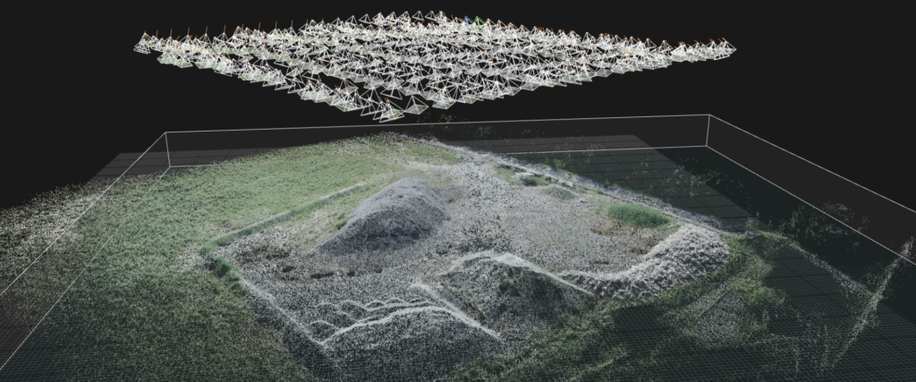
— Video editing software to adjust the video and sample frames from it — Structure from Motion software takes those images, computes the camera positions in 3D space and generates a sparse point cloud of the result — Multi-view Stereo software takes those calibrated cameras and the sparse point cloud and densifies it. It then takes that dense point cloud and converts it into a mesh, and can go on to use the original calibrated images to texture the mesh
- Starting from a LiDAR scan of a room and trying to view the room from every angle on a computer:
— LiDAR software analyses the scanner data and produces a point cloud — Gaussian Splatting software takes that data and renders it in a 3D environment that can be explored in detail